Implementing a Freevalve valve train in an automotive application
A.A. Möller, Freevalve AB, Ängelholm;
Abstract
Freevalve has developed cam-less valvetrains since early 2000’s and applied different versions of the technology on various engines and vehicles for over ten years. Two rolling demonstrators were presented in public in 2016. Since then Freevalve has been working on the commercialization of its technology with key customers in several market segments.
The significant fuel savings achieved with the demonstrators presented 2016 is what has caught the interest from motor media and generated most of the publicity around Freevalve’s pneumatic valve-train. It is however the conceptual change of engine design freedom as well as operational freedom that makes most of the difference for the engine design departments and makes the biggest contribution at the bottom line.
A Freevalve valve-train system can replace several auxiliary functions such as throttle, EGR and wastegate. It can also support functions and operational modes which are more complex to realize; such as seamless cycle switch to various degree of Miller, or Atkinson, do other stroking than 4-stroke, operate realistic Divided Exhaust Period (DEP) and provide full freedom for any cylinder deactivation scheme. Continuous adjustment of the intake stroke does also allow higher geometric compression ratio, which has been successfully applied in existing projects. This in turn paves the way for efficient multi-fuel operation on various renewables.
With a complete solid mechanical de-coupling of the valvetrain to both the engine block and any mechanical driver, the design freedom increases substantially, which is even further enhanced by the compact measures of the valve actuators. Examples of this freedom will be demonstrated with its implications on the engine’s auxiliary component design while the Freevalve valve-train operates several of the mentioned functions.
1. General comments
Freevalve is currently active with customer engine development projects within a wide range of ICE powered sectors. Two generations of in-vehicle installations have been made, the SAAB 9-5 2.3t in 2008 and the Qoros 3 in 2016. Pictures shown and specific data presented in this paper do only origin from the more recent Qoros 3 engine, which has been shown in public jointly by Freevalve and the customer. The Freevalve technology has however evolved substantially since 2016, but this more recent installation related information can only be referred to in general terms, where applied to multiple not yet public customer projects.
2. Enable fuel efficient concepts by introducing a cam-less valvetrain
The main improvements in fuel efficiency (14 %) demonstrated on the 4-cyliner Qoros 3 engine were achieved on part load by increased compression ratio (9,0:1 → 10,5:1) and by throttle-less operation. The latter was achieved by a combination of valve lift modulation and late intake valve closing (LIVC/Atkinson cycle), or timing-controlled duration in more general terms. Timing control of the valve duration is the main instrument for regulation of the engine output with a Freevalve cam-less valve train, while lift is a secondary control parameter, mainly used for optimization of the parasitic losses.
Divided Exhaust Period, DEP, has been investigated several times in history, but not made it to the market for several reasons. The potential is said to be great [1]; such as up to 4 % lowered BSFC from improved scavenging efficiency and around 5 % lower BSFC from lowered back pressure, both at part load, while WOT BSFC can improve over 10 %. In case of the Qoros 3 engine, the most significant isolated benefit from the DEP concept was better low-end torque; 184 vs. 141 Nm (+30%) at 1250 rpm. One part of the improvement in low end torque is a different turbine matching, enabled by the reduced maximum exhaust gas flow. As a secondary effect, DEP was the enabler for the increase in compression ratio, which required efficient scavenging to avoid a severe knock limitation.
3. Multi fuel adaptation with variable dynamic compression
Outlined since the early days of engine prototyping and implemented just lately in ongoing development projects, the geometric compression ratio has been elevated even further for optimal thermodynamic efficiency with alcohol fuels, such as E85. In numbers, we are talking around 13-14:1 for boosted vs. naturally aspirated applications. This can be compared to ~9:1 for the PFI TC multi-fuel engines we saw about 10 years ago and 10:1 for the more recent DI TC engines, while the naturally aspirated has had a compression ratio of around 11:1.
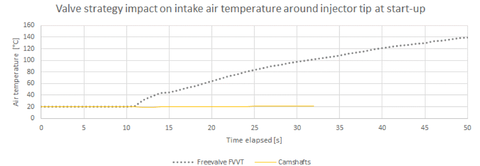
By applying throttle-less EIVC, or LIVC, strategies for shortened intake stroke, the effective compression ratio can be reduced to levels compatible with regular gasoline knock limitations on lower engine speeds. The benefit is full power and efficiency potential from the more knock resistant renewable alcohol fuel, while the drawback is reduced power output during gasoline fuel operation. Besides the implications on normal engine operation, the Freevalve cam-less valve train do also play an important role in cold start conditions, where the high vaporization energy and high mixture threshold for alcohol fuels is a challenge that traditionally calls for higher mixture of fossil gasoline and unnecessary rich mixture during start up. A special valve event pre-heating mode was back in 2010 demonstrated to generate 20 °C rise in the intake air temperature in 3,5 seconds, within the ALK100 project with SAAB and Finnveden Powertrain.
5. Replacing auxiliaries with a multi-functional valvetrain
Several auxiliary functions have been demonstrated possible to achieve with the Freevalve cam-less valve train for a turbo charged SI engine.
Throttle
The Qoros 3 engine was operated throttle-less, even though the throttle was present as a safety device on prototype level. Two concerns need to be addressed to finally exclude the throttle in serial production, that is idle speed stability and providing vacuum for other auxiliaries, such as fuel vapour recovery.
EGR
EGR was handled completely internally by the valve events.
Wastegate
Wastegate is a non-issue with Divided Exhaust Period, where the ratio of turbine to by-pass exhaust gas flow is adjusted by the individual exhaust valve events, leading to larger operating range of the flow routing.
VGT
Another built in feature in a seamlessly variable turbine to by-pass ratio is that the exhaust gas flow is adopted to the turbine, instead of the opposite. In a variable geometry turbine, the turbine geometry is adopted to the exhaust gas flow. This feature has the potential of achieving higher turbine efficiency [2].
Switching cams
Even though they are not clear auxiliary components, dedicated fixed cam-lobes and actuators for cylinder deactivation and/or Miller/Atkinson cycle operation are completely replaced by the core functionality of the Freevalve cam-less valve train. As referred to above, Atkinson cycle type has been applied during part load, which happened to be a better match for that specific engine design than the Miller cycle.
Cylinder deactivation was not implemented in the control system at that time. Today it is available as an arbitrary de-activation on demand for a rolling scheme such as 8-, or 16-stroke operation, for example.
Implications for the drive train
A function outside the engine which the Freevalve cam-less valve train has been promoted to support in the past is the Koenigsegg Direct Drive, where a throttle-less system brings big savings in part load operation at higher than usual engine speeds. A more modest support for the drive train is for gear matching with an automated manual transmission. The Qoros 3 engine was connected to a DCT, which basically could be simplified to a single clutch automated transmission with some calibration, since the cam-less and throttle less system has such a fast-transient response in both acceleration and deceleration of the engine.
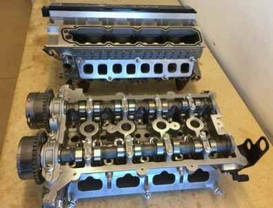
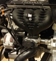
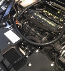
5. Increasing design freedom by de-coupling head and block
Based on the Qoros/Chery 1600 cm3 4-cylinder turbocharged dual-VVT SI engine, a new cylinder head was developed. The complete engine was presented in public in 2016 together with the installation in the Qoros 3 car. Within this engine project, Freevalve has demonstrated a range of possible design changes to the cylinder head architecture, when only the cooling jacket interface remained unchanged among the shared functions with the bottom end.
Below are the design changes listed with implemented, or possible next step design changes, mentioned:
- Camshafts
replaced by valve actuators enables:
- Upright and splayed valves, which in turn enables:
- Increased compression ratio
- Larger design freedom for combustion chamber design
- Larger design freedom for intake and exhaust port design (more upright intake ports were applied)
- Lower total height by ~50 mm
- Increased vehicle exterior design freedom under pedestrian collision constraints
- Or reduced engine compartment size, for commercial vehicles
- Upright and splayed valves, which in turn enables:
- Removed
cam shaft transmission means:
- Shortened engine block by ~70 mm (for an assembled engine)
- Elimination of chest cover with fasteners and eventual sealings
- Shortened crank shaft
- Elimination
of oil consumers in the cylinder head lead to:
- No upper oil gallery, supply or return lines, required
- Reduced oil pump capacity
- Reduced oil pump size
6. Reducing engine size and weight by introducing a cam-less valvetrain
For the Qoros 3 engine, the total engine weight savings came out at over 20 kg, while in case studies on other turbo charged 4-cylinder SI engines, we normally see a weight reduction in the range of 10 kg, or more.
Replacing mechanical cam-shafts with pneumatic valve actuators does however require additional auxiliary components, which needs to be incorporated in the packaging. The main components are:
- Top
End Control System
- The valvetrain control unit executing the ECU’s valve opening/closing requests
- Sensor data processing
- Auxiliary system control
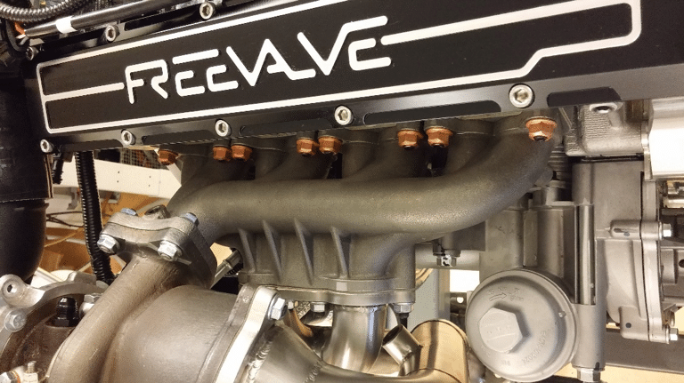
- Air
compressor [Figure 4]
- Creating the pressure difference over the valve actuators
- Pressure source for adjustment of pneumatic spring stiffness
- Oil
pump
- Providing oil for passive hydraulic valve latch and valve seating damping
- Providing oil for thermal management in the compressor at peak loads
- Oil
cooler
- Necessary when the oil serves the compressor thermal management
As mentioned initially, even though a number major components have been added, a substantial weight saving can still be achieved. The packaging on the other side is not a given. Here is how we deal with it:
Top End Control System
Currently the Top End Control System is of the size of an ECU. As with all signal processing devices, short cables are preferred, but a remote location installation is possible, if packaging is a constraint. At the time for the Qoros 3 engine installation, the current level of automotive standard electronics was not developed and could hence not be installed near the engine.
Air compressor
In the case of the Qoros 3 engine, the air compressor was incorporated in the belt circuit in a low position which did not add to the overall effective engine footprint. A similar installation has been applied to both earlier and later projects. Electric driven compressors, projected for HEV’s, may be installed slightly remote from the engine, but as a general preference for energy efficiency and installation simplicity, the air compressor should be installed as close as possible to the cylinder head where the air consumers are located.
Oil cooler
An oil cooler has not been implemented in previous vehicle installations but is generally designed in along the engine block on the cold side, as an oil-to-water heat exchanger, for new engine designs. In the Qoros 3 car, a return air cooler [Figure 5] provided sufficient cooling for the auxiliary system and the unit was located horizontally above the regular radiator package.
Oil pump
The electric oil pump, including a receiving volume of ½-1 litre, was in the Qoros 3 vehicle mounted partly below the engine oil sump, but may as well be installed remotely in the engine compartment if that is more favourable from a packaging point of view.
7. References
Conference proceedings:
[1] Roth, D. and Becker, M.: Valve-Event Modulated Boost System: Fuel Consumption and Performance with Scavenge-Sourced EGR. SAE Int. J. Engines 5(2):2012
Theses and dissertations:
[2] Grundmalm, S.: Divided Exhaust Period on Heavy-Duty Diesel Engines. Licentiate thesis. KTH 2013